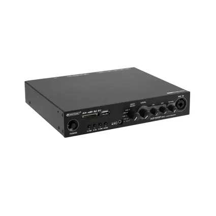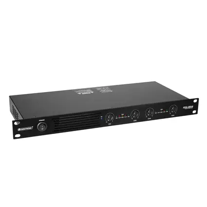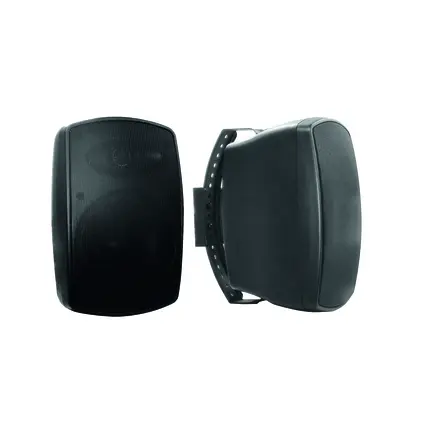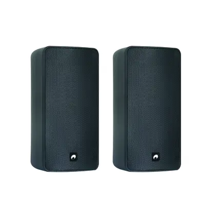
Whether in hotels, department stores, office buildings, or warehouses, extensive speaker systems are often installed to play background music or make announcements. Installing such systems does pose certain challenges. With standard low-impedance wiring, thick and expensive cables are required, which are difficult to install over long distances. The quality loss is quite high, and there is also the risk of overloading the amplifier. To avoid this risk, complex series-parallel connections are unavoidable, which doesn't make things any easier. Individual speaker control is also only manageable with significant effort. A simple and elegant solution to these problems is the use of the 100-volt technology, also known as ELA (electrical loudspeaker system).
Contents
1. How it works:
In a conventional speaker system, like those used in the Hi-Fi and PA sectors, speakers are directly connected to an amplifier. A relatively large current, of several amperes, flows through the cable, requiring large cable diameters and short cables. In ELA, which is particularly suitable for long cable runs, a transformer is connected downstream of the amplifier. This transforms the amplifier's voltage to 100 volts at full modulation. (The transformer is usually integrated into the amplifier.)
At the location of each speaker, a step-down transformer reduces the 100 volts back to a voltage suitable for the speaker. (The transformer is usually mounted in or on the speaker.) The two transformers can have different watt ratings: the amplifier has a transformer for 100 watts, while the speakers have one for 10 watts. The whole system works similarly to a high-voltage line. The high voltage keeps the current low and minimizes line losses over longer distances. The major advantage of ELA technology is that all additional speakers can be connected in parallel to the main cable.
The wiring of the speakers is thus extremely simple. The high voltage results in only a small current flowing through the cables, allowing for long cable paths with a small cable cross-section.
2. Example Calculation:
We need a system for a multipurpose hall consisting of 32 speakers with 8 ohms, each with a maximum power of 10 watts. The last speaker is 100 meters away from the amplifier.
The minimum cross-section for a low-impedance system is calculated as follows: By series-parallel connecting the 32 speakers (four in series, eight of these series connections in parallel), we achieve an optimal impedance of 4 ohms, and the total power is 320 watts, resulting in a maximum current of almost 9 amperes in the system (according to P = I² x R). To not exceed the permissible 3% voltage drop, in our case only about 1 volt (according to U = P / I), a cross-section of 32 mm² is required for this system (according to A = (I · Þ · 2 · L) / Uv). If we transform the maximum voltage to 100 volts, the current reduces to 3.2 amperes (I = P / U) and the required cross-section is only 4 mm². The total of 33 small transformers needed for our system costs only a fraction compared to the wiring from the low-impedance system calculation.
Furthermore, the installer does not need to worry about the impedance of the system or even construct a complicated series-parallel connection like in the above example, but only needs to match the total power of the connected speakers with the amplifier being used.
Another advantage is the adjustable volume of each speaker through different transformer windings—either at the speaker itself or through a pre-installed volume control. This allows the volume to be perfectly adjusted to the environment. The 100-volt technology is thus the first choice for use in office buildings, warehouses, sports fields, churches, public facilities, large restaurants, and hotels.
In the past, the 100-volt technology was often criticized for poor quality. Today, thanks to significant advances in audio transformer technology, this criticism is no longer valid. It is no longer a problem to transmit the frequently required frequency range of 20Hz to 20 KHz even at high power levels of more than 100 watts using transformers. The listener cannot discern any sound quality difference. Also, the mono transmission used in most systems does not result in any quality loss for typical applications (speech announcements, background music). On the contrary: as people move within the sound-covered area, their stereo image would constantly change, leading to unwanted frequency cancellations. The prerequisite for sound quality is, however, the use of correct, suitable, and powerful amplifiers and speakers. Elaborate music sound systems are usually not realized with ELA but are not excluded.
3. Integration of a Microphone into the System
If permanent background sound needs to be complemented with temporary automated or manual announcements, this is immediately possible with most ELA amplifiers thanks to built-in microphone connections and integrated preamplifiers.
The amplifiers of the OMNITRONIC MP/MPZ/MPVZ series also feature an adjustable talkover function that automatically lowers the music volume when a signal is present at the microphone input.
Additionally, when used manually, a signal tone can be activated on the amplifier before the announcement. This would only be possible with a low-impedance system by using an additional, special mixer.
4. Fewer Problems with Room Acoustics by Using Many Small Speakers
While in multipurpose buildings and churches, one often has to contend with complicated room acoustics and, for aesthetic reasons, cannot always rely on mechanical aids like strategically installed sound absorbers on the room sides and ceiling or reflectors over the lectern to reduce comb-filter effects and other acoustic problems, an ELA allows for much lower individual levels with far less diffuse sound and a more favorable reverberation time due to decentralized arrangement (keyword: speech intelligibility). The smaller dimensions of the speakers to be installed also allow for easier integration into the environment. Moreover, ELA speakers are usually available in different colors.
5. More Reliability through Ring Circuit
A problem with many ELA installations is the long cable runs and the associated risk of failure. If the cable is interrupted at any point, all subsequent speakers inevitably fail. One way to circumvent this problem without integrating an expensive and complex line monitoring system is the installation of a ring circuit.
Here, the signal is simply looped back from the last speaker box of the existing installation to the amplifier. It is essential to ensure correct polarity of the wiring in this setup! Using this technique, the system is only adversely affected by a simultaneous interruption of the cable in two different places. Do not try this with a low-impedance system!
6. Combining an ELA with Low-Impedance Speakers and Active Boxes
Depending on the installation location, it may be necessary to integrate low-impedance speakers or active boxes into an existing ELA. For this, the 100-volt signal can be converted into the desired signal using special transformers ELA-T10 to T20 or the converter ELA-100V-2-L from OMNITRONIC.
Avoid connecting active or low-impedance speaker boxes directly to a 100-volt signal! If ELA components are to be connected to an existing low-impedance system, 100-volt adapters are available.
